***WARNING: For Best Video Resolution, it is critical to select 720p HD resolution in the youtube "settings" at bottom right of the player. The 360p default setting won't yield good enough resolution to see the details. It will take several seconds before the High Resolution kicks in, so you will need to restart the video from the beginning when the High Resolution is active and select to view the video in "Full Screen Mode" for best experience...***
*** HOW WELL DOES TARP PERFORM? ***
ANALYSIS OF REAL-WORLD EXAMPLES OF LOW EIRP QSO
IN ORDER TO DEMONSTRATE TARP PERFORMANCE
CONTEXT
The real-world examples of QSO presented in this section are meant to demonstrate TARP performance on the receive side (RX), and give a taste of what it is capable of delivering on the transmit side as well (TX). The analysis below also provides an opportunity to highlight some of the most powerful features of TARP. But before going through the analysis in question, it is important to provide some context to the whole matter first.
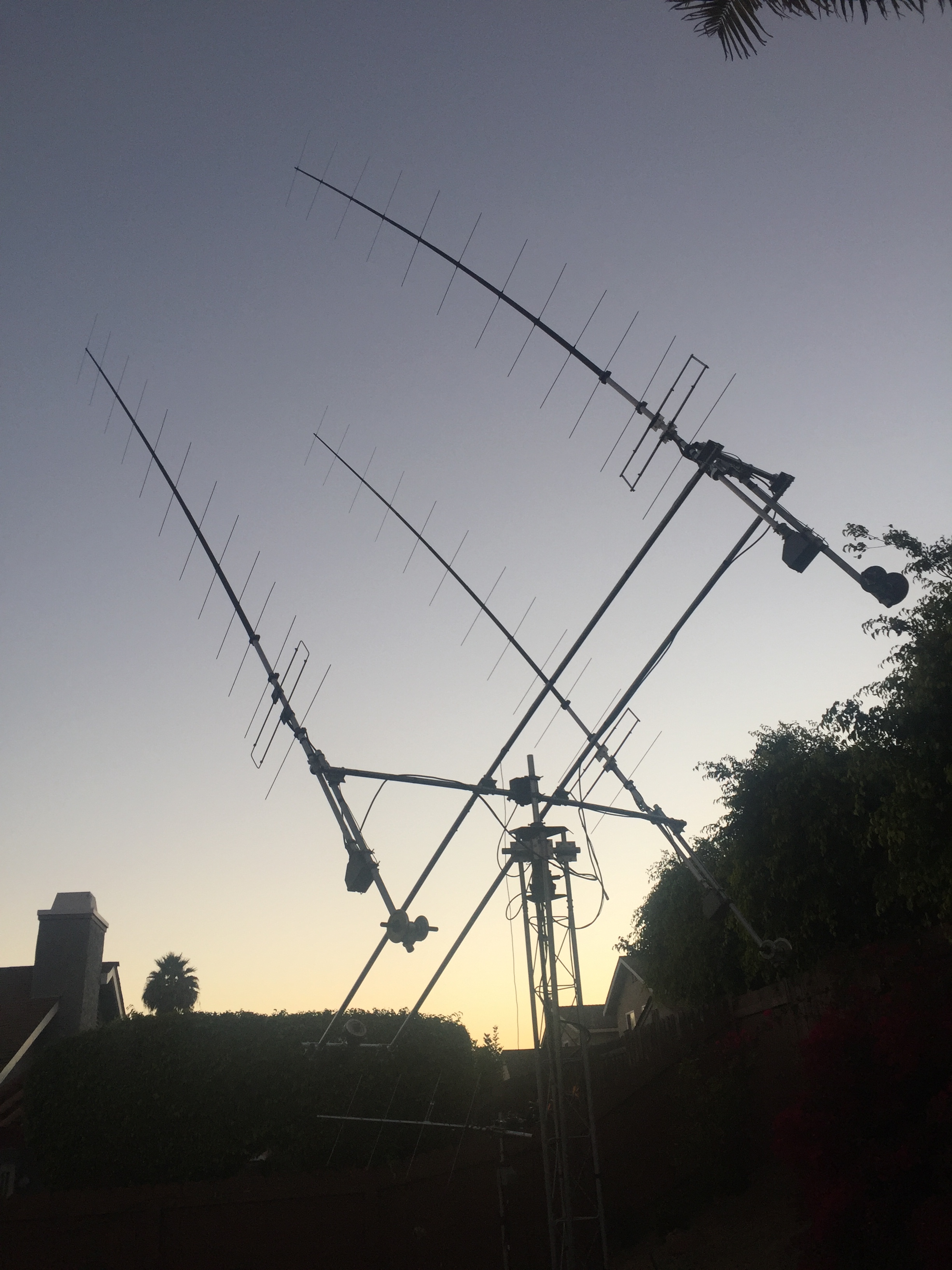
The satellite picture to the right shows my QTH, which is located in a very densely populated area of the city. In the world of EME communications, this represents a very hostile environment from a noise perspective. In addition to the intensity of the surrounding city noise itself, there are powerful transmission towers all around that have the potential to create serious desensing and IMD.
Consequently, one must realize the fact that being able to decode ultra-weak signals from very low EIRP stations in such a noisy environment is a significant challenge that can be an order of magnitude greater in difficulty than it would be for let's say a station located in the country or in a very quiet rural area where the population density and corresponding noise generation are far lesser in general.
I am saying this by experience where when I first started building EME antennas, the prototypes that had significant flaws allowed this strong local noise to penetrate my system resulting in receive penalties that were easily in the order of 5 to 8 dB of extra noise. Below ~20 degrees in elevation, there is an intense "noise swamp" where the noise floor may increase by more than 10 to 15 dB depending on the AZ direction. EME operation at low elevations is hardly possible.
In such noisy environment, nothing can be left to chance. Any station setup flaw or antenna weakness will quickly translate into a massive noise pickup resulting in a severe receive performance penalty. Therefore, it is important to evaluate TARPreceive performance from that very perspective. One of the main value propositions of TARP is precisely to maximize the RX performance and open the way for EME practitioners to operate from very noisy environments without being affected by it in a significant way.The videos and examples below provide hard evidences supporting that claim.
EXAMPLE #1:
Video:
GM4VVX (Clive) and I made an initial QSO using his full available PA power output of 400 watts into a "Vine" Single Yagi 10-element during his Moonset. Per my request, Clive generously accepted to greatly reduce his power output and retry a QSO with me but this time, using only 120 watts instead (75 wattsequivalent at the antenna feed). The video shows the low power QSO in question.
***WARNING: For Best Video Resolution, it is critical to select 720p HD resolution in the youtube "settings" at bottom right of the player. The 360p default setting won't yield good enough resolution to see the details. It may take a few seconds before the High Resolution kicks in, so you will need to restart the video from the beginning when the High Resolution is active and select to view the video in "Full Screen Mode" for best experience...***
ANALYSIS:
1) The QSO
Clive was running 120 watts (PA output) into a "Vine" Single Yagi 10-element at his Moonset. After the QSO, we exchanged several emails in order to quantify the loss in his TX line which ended-up being calculated at 2.1 dB. This means that the RF power left at the antenna feed was more in the order of 75 watts. Per the video, best signal received at KK6FAH was -26dB on the "OOO" and the "RRR" was decoded at -29dB. My best signal at Clive's QTH was -20dB. This data and the video provide hard evidences that TARP is capable of amazing things.
The table to the right shows the calculated Effective Isotropic Radiated Power (EIRP) at different Ground Gain levels. Obviously, there is no way to know how much Ground Gain was in effect during our low EIRP QSO. It is probably safe to assume that there was less than 6dB of Ground Gain since to achieve such figure, the terrain and ground composition have to be ideal which is rarely the case in practice. Since there was clearly some good Ground Gain acting up during the QSO, it is also probably safe to assume that there was more than just 1 dB in effect, so it is most probable that the Groud Gain in effect was in the 2 to 5dB window. This means that the corresponding EIRP range would be from 3300 to 6600 wattsrespectively per the table to the right.
2) Performance Extrapolation/Normalization
One interesting thing we can also do with this data is to perform a performance simulation by simply extrapolating predicted signal strengths using the actual QSO as basis. The extrapolation and normalization performed here represent the weakest signals that TARP should be able to decode in order to produce a viable QSO. In other words, the normalized figures give a taste of TARP best receive performance achievable under a fix set of conditions.
For instance, considering that the "OOO" wa decoded at -26dB and the "RRR" -29dB, we can safely postulate that if the power would have been further reduced by 2dB, the same sequences would have been decoded at -28dB and -31dB respectively. Could a QSO have resulted from such weak signals? Absolutely. Per Section 44 on this website, WSJT decode simulations on hundreds of samples show that there is 66% chance of decode on a single sequence at -28dB for non-shorthands ("OOO" in this instance), and 92% chance of decode for a shorthand at -31dB ("RRR" in this instance). This means that most likely, decodes would have been recorded after 1 or 2 sequences max., and such QSO would have been successful.
A 2dB reduction means that the same QSO would have been possible with only 47 wattsat the antenna feed of the Single Yagi 10-element, which is quite remarkable. The corresponding EIRP (watts) are calculated at the bottom right of the performance table. Based on the above reasoning, one could postulate that TARP would have been capable of decoding EME signals in the 2100 to 4100 watts EIRP range on that particular day based on the conditions present at the time. Again, these figures are extrapolated based on the reasonable assumption that the Ground Gain contribution during the QSO with Clive was in the range of 2 to 5dB.
3) Polarity Flexibility
It is interesting to note that TARP polarity had to be set to 140 degrees in order to maximize Clive signals. If a fix H/V antenna system would have been employed instead of TARP, there would have been an automatic penalty in the order of 2.3dB versus HPOL and 3.8 dB versus VPOL. In many if not most cases, such penalty can be a killer for low EIRP QSO. It is possible that Faraday may shifted the polarity more favorably after a while, but that does not always happen fast enough where favorable Ground Gain windows can be very short and the signal may already be gone or the Moon may have already set by the time Faraday has done its job. This is a very concrete demonstration of one of the key value proposition of TARP, where absolutely polarity flexibility is available so optimum polarity can be set within seconds and valuable QSO can be realized while the Moon window is present or the conditions are most favorable between the two stations.
EXAMPLE #2:
Video:
This case is very similar to the example #1 above. An initial QSO was made with G4TRA (Steve) using his maximum allowable power output of 400 watts into a "Tonna" 11-element Single Yagi at his Moonset. In order to challenge TARP receive performance, I asked Steve G4TRA to reduce his output power by half and retry a full QSO with me. Steve accepted and reduced his power down to 200 watts only (130 watts equivalent at the antenna feed). In order to push the envelope even further, Steve decided to reduced his power to only 100 watts during the "73" sequence (65 watts equivalent at the antenna feed). The video shows the complete QSO in question and the successful decode on the "73" as well. The traces from the previous QSO at 400 watts are still visible when the video begins.
***WARNING: For Best Video Resolution, it is critical to select 720p HD resolution in the youtube "settings" at bottom right of the player. The 360p default setting won't yield good enough resolution to see the details. It may take a few seconds before the High Resolution kicks in, so you will need to restart the video from the beginning when the High Resolution is active and select to view the video in "Full Screen Mode" for best experience...***
ANALYSIS:
1) The QSO
At 200 and 100 watts of PA power output, good traces were obtained and the QSO seemed effortless. Similarly to what was done with Clive in the example #1, the TX line loss was calculated post QSO and estimated to be in the order of 1.89dB. This means that the actual power at the antenna feed was 130 watts for the "OOO" and "RRR", and half that, i.e. 65 watts for the "73" sequence. Per the video, best signal received at KK6FAH was -25dB on the "OOO" and the "RRR" was decoded at -28dB. My best signal at Steve's QTH was -17dB. If we make the same Ground Gain assumptions described in the example #1, we end-up with a corresponding EIRP likely range of 5400 to 10700 watts per the table to the right. The EIRP on the "73" is obviously half these figures.
2) Performance Extrapolation/Normalization
If we perform the same extrapolation exercise as shown in the example #1, but this time applying a 3dB reduction, we would end up with "OOO" decoded at -28dB and the "RRR" decoded at -31dB, which have the same % probability of decode mentioned in the example #1. A 3dB reduction out of 130 watts means that the same QSO would have been possible with only 65 wattsat the antenna feed of the Single Yagi 11-element. The corresponding EIRP (watts) would have been in the 2700 to 5350 watts range, again assuming Ground Gain contribution in the 2 to 5dB range. The calculated figures are shown at the bottom right of the table.
Interestingly, TARP extrapolated "best receive performance" achievable in the Example #1 and #2 above are relatively close, let's summarize them:
GM4VVX:47 wattsat the antenna feed of the Single Yagi 10-element or 2100 to 4100 watts EIRP
G4TRA: 65 wattsat the antenna feed of the Single Yagi 11-element or 2700 to 5350 watts EIRP
Let's use a 3rd and final example but this time, with signals that are much stronger EIRP station and see if we fall within the same range.
EXAMPLE #3:
Video:
This QSO with G4HSK (Steve) was straight forward and quite impressive from a signal strength standpoint considering his station size. Steve was running 400 watts at the antenna feed of a 2X8H I0JXX array.
This particular example is not truly a low EIRP QSO per say. It is mainly intended to be used as an additional datapoint in order to extrapolate and normalize TARP best receive performance achievable and see how this line up with the previous 2 examples.
G4HSK traces were outstanding for a station of its size and as shown throughout the video, many portions of sequences were very audible (e.g. "RRR"). The best signal received at KK6FAH was -17dB and my best at Steve's station was -16dB. See Steve screenshot to the right. If we make the same Ground Gain assumptions described in the example #1-2, we end-up with a corresponding EIRP likely range of 32300 to 64500 watts. Let's extrapolate from there and see what these figures represent once they are normalized.
2) Performance Extrapolation/Normalization
If we perform the same extrapolation exercise as shown in the example #1-2 above, but this time, applying a 9dB power reduction, we would end up with "OOO" decoded at -28dB and "RRR" decoded at -26dB. At these levels, the % probability of decoding "OOO" on a single sequence at -28 dB is 66% and 100% on a "RRR" shorthand at -26dB. A 9dB reduction corresponds to a power of only 50 watts at the antenna feed.
Once we apply this 9dB power reduction at different Groud Gain levels, we end-up with the figure calculated at the bottom right of the table. For the same assumed 2-5dB Ground Gain contribution range, we are looking at normalized figures of 4100 to 8100 wattsEIRP.
CONCLUSION
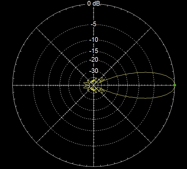
As demonstrated in this analysis, TARP performance on both receive and transmit are extremely promising. The examples above provide strong evidences that TARP unique features such as its "ultra-clean" radiation pattern are producing the expected results. TARP effectiveness on the transmit (TX) side is quite compelling as well. In the examples #1-#2-#3 above, best signals of -20dB, -17dB and -16dB respectively were decoded by the small stations on the receiving end.
For the 3 QSO analyzed above, the actual power at the antenna feeds and the corresponding EIRP figures calculated which assume a range of 2 to 5 dB of possible Ground Gain contribution are summarized below:
GM4VVX:75 wattsat the antenna feed of a Single Yagi 10-element or 3300 to 6600 watts EIRP
G4TRA: 130 wattsat the antenna feed of a Single Yagi 11-element or 5400 to 10700 watts EIRP
G4HSK: 400 watts at the antenna feed of a 2X8H I0JXX array or 32300 to 64500 watts EIRP(this is not a low ERP QSO, but it is used as a 3rd data point)
Once extrapolated and normalized in order to represent the "best receive performance achievable", we end-up with the following figures:
GM4VVX:47 watts at the antenna feed of a Single Yagi 10-element or 2100 to 4100 watts EIRP
G4TRA: 65 watts at the antenna feed of a Single Yagi 11-element or 2700 to 5350 watts EIRP
G4HSK: 50 watts at the antenna feed of a 2X8H I0JXX array or 4100 to 8100 watts EIRP
Based on the documented evidences and analysis above, it is reasonable to postulate that TARP is capable of QSO with extremely small stations in the most likely range of 2100 to 8100 watts EIRP in periods of low degrade. Many more QSO were made with low EIRP stations (all single yagis), some with and some without any Ground Gain. They all point to the fact that TARP performs surprisingly well on both TX and RX. Its RX performance is particularly promising considering the fact that my station is located in a densely populated area which is very noisy and unfriendly for EME operation. TARP does an incredible job at rejecting the surrounding noise and decoding these ultra-weak signals.
The rotatable polarity feature is an additional extremely powerful asset which enables optimizing polarities for best transmit and receive performance within seconds, and not waste any time waiting for Mr. Faraday to favorably align the polarities, which may never happen when time is limited. Since my QTH is on the West Coast of the United States, the common Moon windows with Europe when the Moon is high enough to escape the city noise are sometimes extremely short, or even inexistent which is the case in periods of low declinations. Having the ability to quickly zero in on the optimum polarities without having to wait for Mr. Faraday is an invaluable asset which allows me to be most efficient and effective with my time.
 FEATURING:
 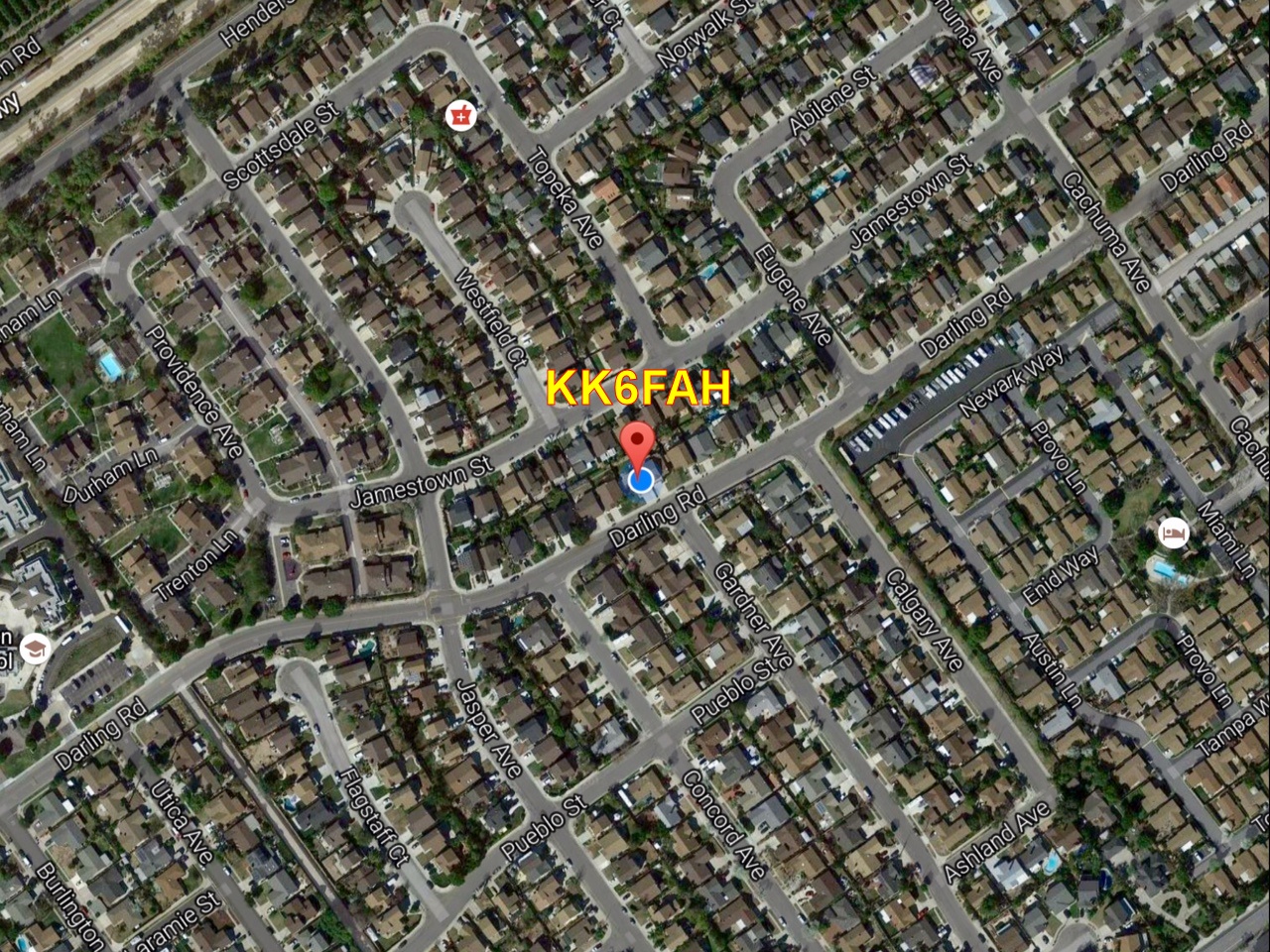 The real-world examples of QSO presented in this section are meant to demonstrate TARP performance on the receive side (RX), and give a taste of what it is capable of delivering on the transmit side as well (TX). The analysis below also provides an opportunity to highlight some of the most powerful features of TARP. But before going through the analysis in question, it is important to provide some context to the whole matter first.
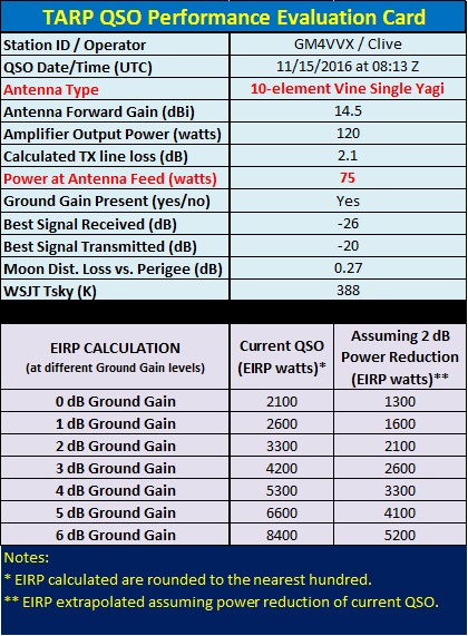 Clive was running 120 watts (PA output) into a "Vine" Single Yagi 10-element at his Moonset. After the QSO, we exchanged several emails in order to quantify the loss in his TX line which ended-up being calculated at 2.1 dB. This means that the RF power left at the antenna feed was more in the order of 75 watts. Per the video, best signal received at KK6FAH was -26dB on the "OOO" and the "RRR" was decoded at -29dB. My best signal at Clive's QTH was -20dB. This data and the video provide hard evidences that TARP is capable of amazing things.
 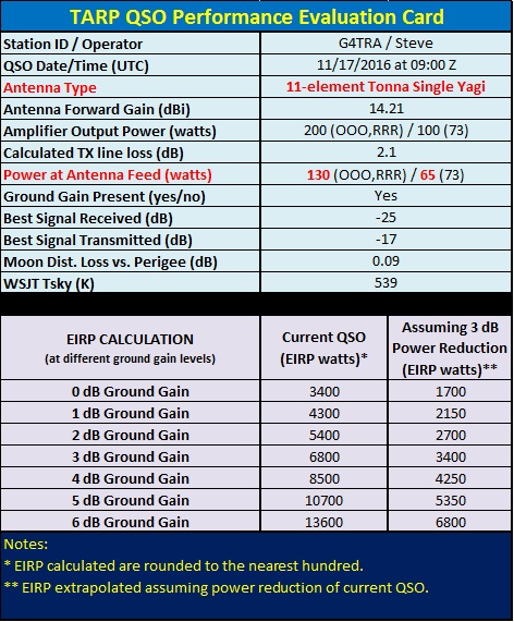 At 200 and 100 watts of PA power output, good traces were obtained and the QSO seemed effortless. Similarly to what was done with Clive in the example #1, the TX line loss was calculated post QSO and estimated to be in the order of 1.89dB. This means that the actual power at the antenna feed was 130 watts for the "OOO" and "RRR", and half that, i.e. 65 watts for the "73" sequence. Per the video, best signal received at KK6FAH was -25dB on the "OOO" and the "RRR" was decoded at -28dB. My best signal at Steve's QTH was -17dB. If we make the same Ground Gain assumptions described in the example #1, we end-up with a corresponding EIRP likely range of 5400 to 10700 watts per the table to the right. The EIRP on the "73" is obviously half these figures.
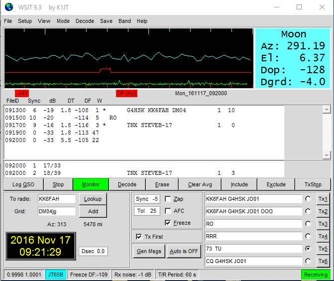 EXAMPLE #3:
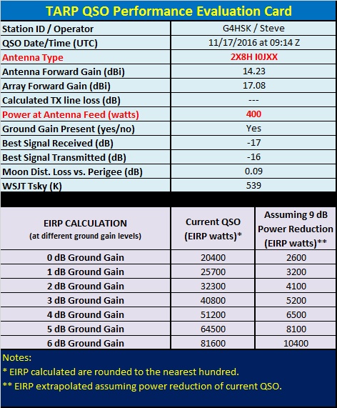 If we perform the same extrapolation exercise as shown in the example #1-2 above, but this time, applying a 9dB power reduction, we would end up with "OOO" decoded at -28dB and "RRR" decoded at -26dB. At these levels, the % probability of decoding "OOO" on a single sequence at -28 dB is 66% and 100% on a "RRR" shorthand at -26dB. A 9dB reduction corresponds to a power of only 50 watts at the antenna feed.