SINGLE YAGI 13-ELEMENT RPOL LFA OPTIMIZED FOR RX OPERATION - LATEST PERFORMANCE UPDATE
(June 28, 2015)
The launch of the "Moon Echo Project" and the initial experiments that followed enabled producing Moon Echos "at will" and opened the way to a host of future studies in the field of EME to my great satisfaction. As a bonus, it was found that the 13-Element RPOL LFA Single Yagi employed was extremely sensitive and yielded a formidable RX performance.
Since the initial setup of that capability, I have been, and continue to optimize that very antenna for best RX operation. For instance, the LNA is now connected directly to the BALUN output, eliminating any losses related to phasing cables, power divider, etc. A 4-MHZ DCI Bandpass Filter immediatly follows, then, 75-foot of LMR 400 Flex coaxial cable leading up to the shack is followed by another DCI Bandpass Filter of 2-MHZ this time, then to the rest of the setup in the shack...
After only a few days of operation with this setup, the RX performance observed has been absolutely fantastic and beyond all my expectations. To my surprise, most of the time, the 13-Element RPOL LFA located in the backyard outperforms the RX performance of the 2X14 RPOL which is located on the roof.
This was highly troubling to me, so I did some initial experiments in order to root cause this phenomenon. Since the LFA antenna design was new to me, I thought that either the difference in performance was due to the LFA design itself, or due to the fact that the 13-Element RPOL LFA antenna in the backyard was simply "less exposed" to urban noise where the 2X14 RPOL array is located much higher up in the air (roof) so it is litterally "sniffing" over an entire city! Very simply put, the 2X14 on the roof has a much higher "Surface Area" of potential noise entry points, where the noise can "attack" and penetrate the antenna from all angles and dimensions, even from the bottom (my own house and negative horizon angles).
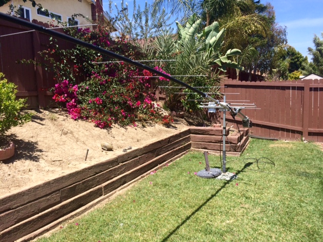
To the contrary, if one looks at the picture of the 1X13 RPOL LFA to the right, one will quickly realize that from a pure dimensional standpoint, when the antenna is closer to the ground, the surface area of the potential noise entry points is highly reduced and much more advantageous. For instance, in this particular case, clearly, no noise can penetrate from the bottom or negative angles (ground/soil). On the North side, there is a little hill and fence which again, may help blocking some of the noise. On the other side, my own house made of concrete my also help blocking some of the city noise, especially since when I do EME, I turn everything off in the house which may generate any noise. The end result is an antenna which is much more "shielded" from the noise compared to the 2X14 located on the roof.
In order to determine whether the lower noise level observed with the LFA (G0KSC design) was due to the design or not, since I had a spare 12-element YU7EF design available hanging on the fence (same design as the 2X14 RPOL), I took relative noise measurements at different AZ/EL with both antennas (which were swapped in between). The AZ/EL angles were made using an approximate method but I figured that this would be a good starting point. Remember that the noise difference between the 1X13 LFA and 2X14 is in the order of 2-3 dB, so if there was to be a systematic difference in performance between the two, I should be able to see it easily.
The results of the experiment are shown in the table below. Considering the uncertainties involved in this experiment, it appears that both antenna designs were about equivalent. These results indicated that most likely, the difference in noise level between the 1X13 LFA and the 2X14 is due to physical location of the antennas (as explained above).As amateur Radio operator, one of our instincts is to put antennas as high up as possible in the air. However, in the case of EME operation, this may be highly counter productive and a fatal flaw where the noise pickup may be highly increased..............
AZ/EL LOCATION #
NOISE LEVEL
13-ELEMENT RPOL LFA (G0KSG)
NOISE LEVEL
12-ELEMENT RPOL (YU7EF)
DIFFERENCE
1
18.5 dB
17.3 dB
+1.2 dB
2
17.0 dB
17.5 dB
-0.5 dB
3
20.0 dB
19.5 dB
+0.5 dB
4
21.0 dB
20.3 dB
+0.7 dB
5
18.2 dB
18.8 dB
-0.6 dB
6
24.6 dB
23.7 dB
+0.9 dB
Since the implementation of the Moon Echo Project setup, I have been able to hear my own echos "at will", that is 100% of the time, even under extreme degrade conditions as demonstrated in Section 27, and even when the TX source of the echo signal is a medium size Single Yagi (my own 1X14/KW) without any Ground Gain (Section 28).
Since then, the RX performance of this system has been challenged through several QSO's and Non-QSO decodes from Low ERP Stations, most of the times without the help of any Ground Gain.
The 1:17 min video to the right shows a short compilation of these. The Low ERP QSO with JH0BBE (Yugi) for instance is an interesting example. First, there was no Ground Gain involved in this QSO. Yugi was using a 4X9V array and only 250 watts of power. In terms of ERP equivalent, after accounting for the additional losses involved in a 4X array compared to a Single Yagi, the output of this particular 4X9V setup using 250 watts is roughly equivalent to a Single Yagi 8-Element running at 1 KW!
It is interesting to note that the quality/intensity of the signals themselves is surprisingly good. In fact, many decodes in the -20dB to -23dB range have been obtained from several Low ERP Stations. Generally, after finding the optimal polarity of the stations of interest, I can litterally hear "all" the stations in the EME Sub-Band, even the very small ones.
CONTRIBUTING FACTORS
I believe that the main reasons contributing to the RX performance of this setup is actually a "combination" of several high impact features such as:
1) Rotatable Polarity Capability (RPOL)
=> Rotatable Polarity capability remains a massive advantage to maximize TX/RX performance by eliminating any losses due to polarity mismatch.
2) Combination of RPOL Rear Mounted Configuration, LFA and I0QM BALUN
=> Produces an ultra clean radiation pattern where current mode is eliminated and there are no metallic structures and conductors in the way of the antennas.
3) Physical Location of the Antenna
=> Antenna is less exposed to urban noise being near ground level as opposed to be high up in the air.
4) Bandpass Filtering
=> Keeps out-of-band signals from interfering, desensing the RX equipment and degrading the overall RX performance.
5) LNA connected directly to the BALUN
=> Eliminates losses associated to coax, power divider, connectors, etc.
My current objective is to further maximize the performance of this RX antenna system, and then it will be scaled-up by adding more units and build an array of these...
The picture to the right shows a "Bent Reflector", which I am currently experimenting with.
More to come, stay tuned...
***WARNING: For Best Resolution for the videos below, it is critical to select 720p HD resolution in the youtube "settings" at bottom right of the player. The 360p default setting won't yield good enough resolution to see the details. It will take several seconds before the High Resolution kicks in, so you will need to restart the video from the beginning when the High Resolution is active and select to view the video in "Full Screen Mode" for best experience...***
 The launch of the "Moon Echo Project" and the initial experiments that followed enabled producing Moon Echos "at will" and opened the way to a host of future studies in the field of EME to my great satisfaction. As a bonus, it was found that the 13-Element RPOL LFA Single Yagi employed was extremely sensitive and yielded a formidable RX performance.
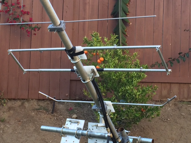 3) Physical Location of the Antenna