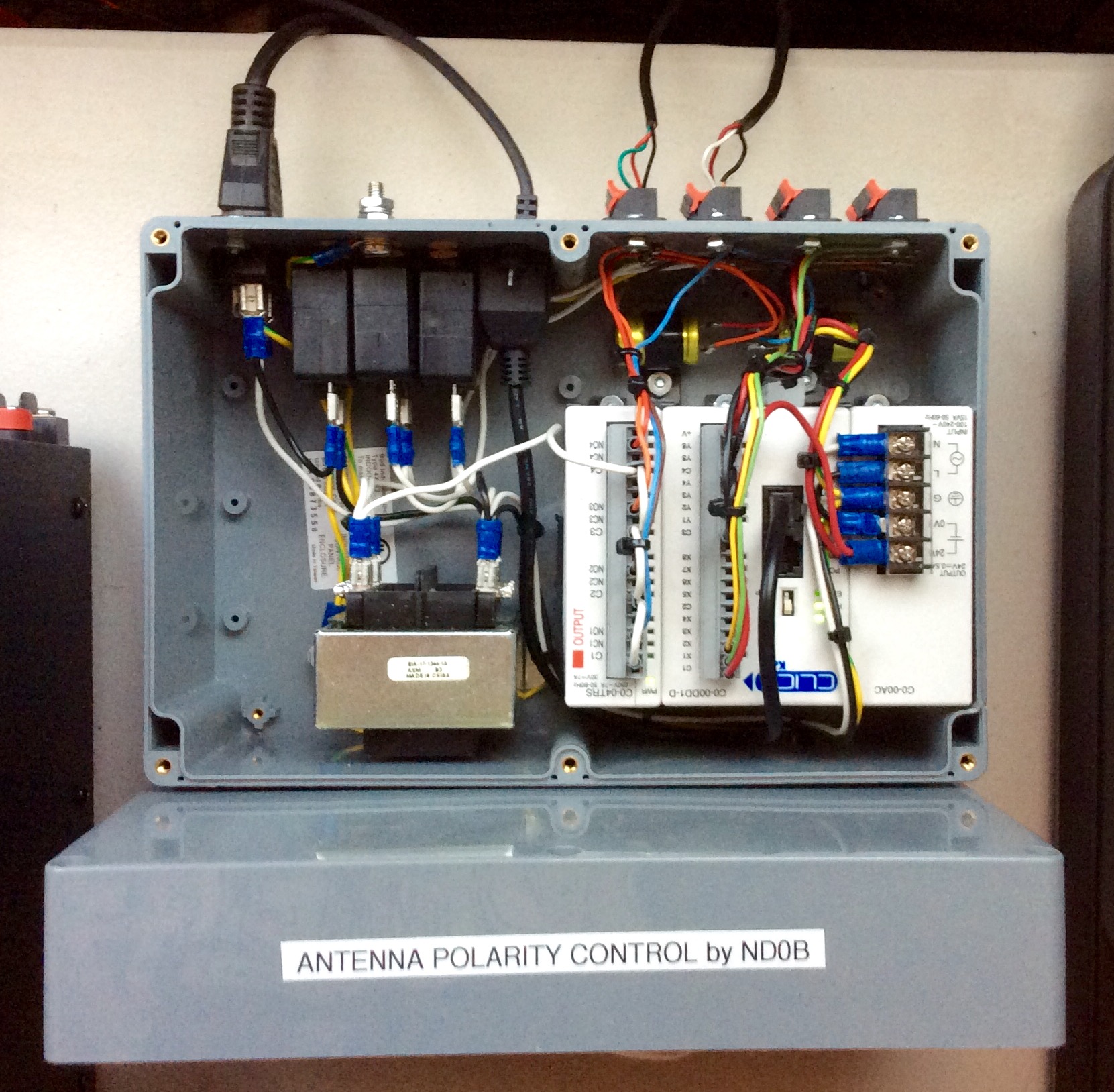
In less than 4 weeks after meeting Bill (ND0B) on the Moon, a USPS package was at my front door... Yes, Bill had achieved the impossible anddeveloped a sophisticated control box with PLC and a prototype application enabling the full automated control of my RPOL system via PC. Bill had also carefully designed the application to interact with WSJT enabling outstanding capabilities. Early on, it became very clear that this was going to open a host of new and powerful possibilities, it was just a matter of spending the quality time to develop and debug the system. It was truly astonishing to me that Bill had put all this together in such a short period of time after our initial contact. All the credit to him for the great work on this!
In the days that followed (and still continuing), Bill and I exchanged an astronomical amount of emails and information about EME and the practical features that would be desirable to implement so we could end up with the best possible product. I truly believe that this system is a dream come true in the field of EME, where it is extremely simple, flexible, cost effective and without compromise.
Below are some of the main features of the system as it stands right now (version 1.0):
***WARNING: For Best Resolution for the videos below, it is critical to select 720p HD resolution in the youtube "settings" at bottom right of the player. The 360p default setting won't yield good enough resolution to see the details. It will take several seconds before the High Resolution kicks in, so you will need to restart the video from the beginning when the High Resolution is active and select to view the video in "Full Screen Mode" for best experience...***
FEATURE #1: Non-Reciprocity Compensation
Non-Reciprocity is a well known phenomenon for most experienced EME practioners. However, the ways to combat the negative impacts of it are not as straight forward, or may come with a significant compromise (e.g. 3dB penalty if one TX circular polarization for instance).
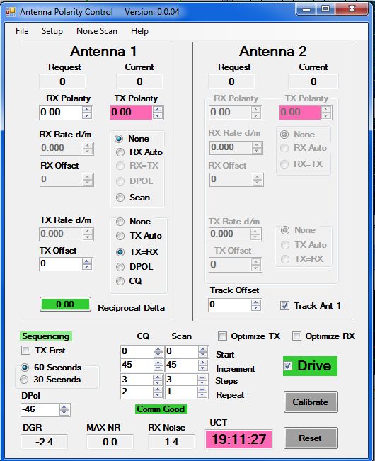
Eliminating Non-Reciprocity effects using this new system cannot be easier and can be achieved without any compromise on the performance. The protocol consists in simply finding the polarity of the station of interest yielding the best trace. After entering the station ID and grid locator in WSJT and selecting the "DPOL" option, the application will automatically extract the Spatial Rotation information (DPOL) from WSJT, calculate and set the optimum TX polarity angle. Between each RX and TX sequence, the polarity offset will be applied and the antennas will physically rotate to match the optimum settings that have been determined. If for some reasons the theoritical offset angle does not work well, the user can also set it manually and easily decouple RX and TX polarity angles.
The video clip to the right shows a small portion of a Non-Reciprocal QSO between ND0B (Bill) and I (KK6FAH). This time, the TX polarity angle offset was set manually (not based on DPOL). The video speed has been accelerated by a factor 4X for convenience. Initially, I could decode Bill but he had no traces from me. As soon as I set the TX offset, Bill started seeing my traces and we were able to quickly wrap up the QSO. The video clip shows how easy Non-Reciprocity can be mitigated using this Application/RPOL system. Below another video this time from the roof showing what the antennas are doing between the RX and TX sequences. The video was purposely produced using short 30 seconds sequences to speed up the demonstration (PS: there was a lot of wind that day...).
FEATURE #2: Noise Mapping
As demonstrated in sections 12, 14 and 16, the polarization of an EME antenna array may have a significant impact on the intensity of the noise level. As shown in section 16 for instance, even 0 and 180 deg. polarities (both HPOL) may behave quite differently from a noise standpoint. Same applied to +90 and -90 deg. (both VPOL) for instance and every other combinations in between and their 180 deg. offset. The impact of the antennas polarization on the intensity of the noise level is particularly accute when there is man made noise involved.
This new RPOL system enables performing a "noise scan" where a full 360 degrees rotation is performed (from -180 to 180 deg), and the noise level is measured and extracted from WSJT throughout the process. The scan produces a nice noise MAP which yield extremely valuable information. The video clip shows the process in question. In this particular example, it is remarkable to see how much difference there is between the different polarity angles. One can see for instance that there is a "sweet spot" at -45 degrees (lower noise) which could surely be exploited...
What are the possible practical applications? Here are some examples:
1) Imagine that there is a fair amount of man made noise on a given day and the user wants to find a polarity that will enable acceptable / optimum RX. The noise map would illustrate the most favorable polarity angles to "hang around" while or until Faraday Rotation favorably aligns the polarity of the station(s) of interest.
2) Let's suppose that the user has a sked with a station that TX circular, obviously, the optimum RX polarity angle would be the one with the lowest amount of noise.
3) A user wants to perform an "Echo Test", once again, the antennas should be "parked" at the polarity yielding the least amount of RX noise.
FEATURE #3: Noise Optimizer
Based on the noise map developed, the RPOL software will enable an easy determination and selection of the most favorable "quadrant" or range of polarities that yield the lowest noise and constrain the antennas rotation within that regime (RX/TX Optimizer). Additionally, the application also indicates which 180-degree reciprocal is the most favorable one (e.g. 0 versus 180 deg or +90 versus -90 deg. for instance).
FEATURE #4: Optimized CQ Routines
Optimized CQ's performed at different TX increments, RX done at same or different polarities.
When and EME practitioner starts a typical CQ run, there is no way to know if the polarity landing on the other side will be favorable or not. When it is not, one typical recourse is to wait that at some point in time, Faraday Rotation will eventually align the polarizations between two stations so a QSO can result. One obvious downside is that Faraday may not rotate fast enought for this to occur within a reasonable amount of time. The use of cross or X pol is an example of way to speedup the process, but typically won't cover the 45-deg pol. in between so a 3 dB penalty may apply.
This automated RPOL system resolves all these issues and significantly decreases the "wait time". A CQ run can be initiated with different TX polarity increments, each of which with a desired/programmable number of repeats at each increment. Very quickly, one or more stations on the other side should be able to decode the CQ's as the polarity alignment will become favorable.
In addition, after a TX CQ sequence, if Non-Reciprocity is present, it is highly possible that a station will reply to the CQ but the station CQing won't see anything. The programmable Optimized CQ Routines are flexible enough so that using the "Scan Function", the RX sequences following the CQ sequences can be performed at different RX polarities. This way, if Non-Reciprocity is present, it will be automatically overcome and a QSO may result.
FEATURE #5: Faraday Rotation Compensation
Using the RX/TX "Auto" mode, the application allows entering a Faraday Rotation Rate (CW or CCW) and the antenna array will follow that exact rate and orientation over time. This can be particularly useful during very long lasting QSO's or while monitoring/exploiting a particular DX window.
Section 9 above shows an example where I monitored and decoded a very low ERP station over a period of 1 hour, and the total Faraday Rotation during that period was well over 200 degrees which required very frequent polarity adustments. It would have been much easier to assume and program a rotation rate and let the application do most of the job (much least frequent adjustments would have been necessary). The video clip to the right shows the Faraday Rotation Compensation feature in action.
FEATURE #6: RX Scan
When an EME operator starts monitoring the EME sub-band searching for traces/decodes, generally, the operator does not really know the polarity of the station(s) of interest. The various polarities can be scanned "manually", but the process can also be done automatically using the RX Scan capability. In a nutshell, RX monitoring can be performed at different polarity increments with programmable repeats and steps so the operator can simply sit down, and wait until traces start appearing on the screen and then lock onto the station(s) of interest.
 In less than 4 weeks after meeting Bill (ND0B) on the Moon, a USPS package was at my front door... Yes, Bill had achieved the impossible and developed a sophisticated control box with PLC and a prototype application enabling the full automated control of my RPOL system via PC. Bill had also carefully designed the application to interact with WSJT enabling outstanding capabilities. Early on, it became very clear that this was going to open a host of new and powerful possibilities, it was just a matter of spending the quality time to develop and debug the system. It was truly astonishing to me that Bill had put all this together in such a short period of time after our initial contact. All the credit to him for the great work on this!